What is a Relay?
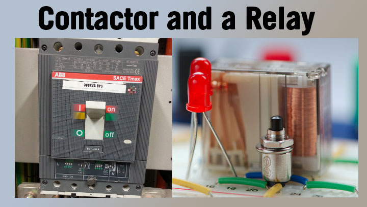
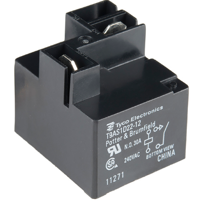
A relay is an electromechanical or solid-state device that serves as a switch to control the flow of electrical current in low to medium-power applications. It consists of a coil, contacts, and an enclosure similar to a contactor. When the coil is energized, it generates a magnetic field that attracts the contacts, either closing or opening the circuit, depending on the relay's configuration. This allows the flow of current through the connected electrical load.
Relays are commonly used in applications with lower current requirements, typically below 15 amperes. They are often employed to control smaller loads or as an intermediary between a low-power control signal and a higher-power load. Depending on the specific application requirements, the contacts in a relay can be made of various materials, such as silver or gold. The enclosure, typically plastic, protects against environmental factors and electrical hazards.
One of the main advantages of relays is their ability to isolate the control circuit from the load circuit. This means that a low-power control signal can switch a higher power load without the risk of electrical interference or damage to the control circuit. Additionally, relays can be designed with multiple contacts, allowing them to control multiple circuits simultaneously. These also provide different switching configurations, such as single-pole double-throw (SPDT) or double-pole double-throw (DPDT) arrangements.
Open/closed contact standards
Relays are designed to operate both normally open and normally closed depending on the required function, but contactors are designed to operate with normally open contacts. This means there is no contactor connection when the coil is de-energized, which is not necessarily true regarding relays.
Easy to remember:
- Normally closed (NC) = Current flows
- Normally open (NO) = Current does not flow
In normally open conditions, no current flow is in its normal or initial state. But energizing it and switching it on will close the contacts to allow it to flow current. On the other hand, normally closed in NC contacts is a condition with a flow of current in its normal or initial state. But contrary to what happens in NO, de-energizing and switching it on will open the contact to stop the current flow. Contactors are typically used to switch high-voltage circuits, while relays are typically used to switch low-voltage circuits.
Applications of Contactors and Relays
- Industrial Applications
- Commercial Applications
- Residential Applications
Installing Contactors and Relays
- Choose the appropriate location: Select a suitable location for the device, considering available space, mounting options, and environmental conditions. Ensure that the device is installed in a clean, dry, and well-ventilated area, away from heat, moisture, or excessive vibration sources.
- Mount the device securely: Use the appropriate mounting hardware, such as screws or DIN rail clips, to securely attach the device to a panel, enclosure, or other suitable surface. Ensure that the device is mounted in the correct orientation, as the manufacturer specifies.
- Wire the device according to the manufacturer's instructions: Follow the wiring diagram and guidelines to connect the device to the control circuit and the load. Use the appropriate wire size and type, as specified by the manufacturer, and ensure that all connections are secure and properly insulated.
- Verify proper operation: Before energizing the device, double-check all connections and ensure that the device is installed and wired correctly. Once the device is energized, test its operation by manually activating the control circuit and observing the response of the load. Verify that the device operates as expected and that there are no signs of overheating, arcing, or other issues.
Troubleshooting and Maintenance
- Inspect the device regularly: Perform visual inspections to check for wear, damage, or contamination signs. Look for signs of overheating, such as discoloration or deformation of the enclosure or contacts. Check for loose or corroded connections, leading to increased resistance and reduced performance.
- Clean the device as needed: Remove dust, dirt, and other contaminants using a soft brush or compressed air. Be cautious not to damage the main contacts or other sensitive components during cleaning. If necessary, use a mild cleaning solution and a soft cloth to remove stubborn dirt or grease, but ensure the device is completely dry before re-energizing it.
- Check the contacts for wear: Examine the set of contacts for signs of wear, such as pitting, erosion, or excessive buildup of contact material. If the power contacts are severely worn or damaged, these may need to be replaced to maintain reliable operation. Consult the manufacturer's guidelines for specific information on contact replacement and maintenance intervals.
- Test the device's operation: Periodically test the operation of the contactor or relay by manually activating the control circuit and observing the response of the load. Verify that the device operates as expected and that there are no signs of abnormal behavior, such as chattering, arcing, or excessive noise.
- Monitor the device's performance: Keep track of the device's performance over time, noting any changes in operation, such as increased response times, reduced contact force, or increased electrical noise. These changes may indicate that the device requires maintenance or replacement.
What is a contactor?
Why a contactor is used?
The Function of Relay
- Control Signal Switching: Relays act as switches to control the current flow in a circuit based on a control signal. They provide a means to open or close a circuit, allowing the control signal to activate or deactivate the load circuit.
- Signal Amplification and Isolation: Relays can amplify weak control signals, enabling them to control larger loads or devices. They also provide isolation between the control and load circuits, safeguarding sensitive control components from high voltages or currents.
- Low-Current Applications: Relays are well-suited for applications with low-current requirements. They can handle small currents, ranging from milliamperes to a few amperes. This makes them suitable for controlling electronic circuits, microcontrollers, sensors, and other low-power devices.
The Function of Contactor
- Power Switching: Contactors are designed to handle the switching of high currents in power circuits. They enable the control circuit to switch heavy loads, such as electric motors, lighting systems, and industrial machinery.
- Continuous Duty Operation: Contactors are built to withstand continuous operation without overheating or malfunctioning. They can handle long periods of operation, making them suitable for applications where the load needs to be continuously powered.
- High-Current Applications: Contactors excel in high-current applications, typically ranging from tens to thousands of amperes. They are constructed with robust materials and heavy-duty contacts to handle the demands of large currents, ensuring reliable and safe operation in high-power devices and systems.


