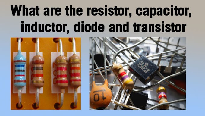
Sort Anwer Resistor, Capacitor, Inductor, Diode and Transistor
- The resistor is an element that opposes the flow of current.
- The capacitor is a device used to store an electric charge in the form of a static field separated by 2 insulators
- The inductor is also a charge-storing device but in the form of a magnetic field
- A diode is a semiconductor device with two terminals, typically allowing the flow of current in one direction only
- The transistor is also a semiconductor device used for amplification and sometimes rectification.
What do they do in an electric Component circuit?
- Resistor
- Capacitor
- Inductor
- Diode
- Transistor
What is a Resistor?
A passive electrical component with two terminals that are used for either limiting or regulating the flow of electric current in electrical circuits.
The main purpose of a resistor is to reduce the current flow and to lower the voltage in any particular portion of the circuit. It is made of copper wires which are coiled around a ceramic rod and the outer part of the resistor is coated with an insulating paint.
A resistor is a passive two-terminal electrical component that implements electrical resistance as a circuit element. In electronic circuits, resistors are used to reduce current flow, adjust signal levels, to divide voltages, bias active elements, and terminate transmission lines, among other uses. High-power resistors that can dissipate many watts of electrical power as heat may be used as part of motor controls, in power distribution systems, or as test loads for generators. Fixed resistors have resistances that only change slightly with temperature, time, or operating voltage. Variable resistors can be used to adjust circuit elements (such as a volume control or a lamp dimmer) or as sensing devices for heat, light, humidity, force, or chemical activity.
Resistors are common elements of electrical networks and electronic circuits and are ubiquitous in electronic equipment. Practical resistors as discrete components can be composed of various compounds and forms. Resistors are also implemented within integrated circuits.
The electrical function of a resistor is specified by its resistance: common commercial resistors are manufactured over a range of more than nine orders of magnitude. The nominal value of the resistance falls within the manufacturing tolerance, indicated on the component.
The notation to state a resistor's value in a circuit diagram varies.
One common scheme is the RKM code following IEC 60062. Rather than using a decimal separator, this notation uses a letter loosely associated with SI prefixes corresponding with the part's resistance. For example, 8K2 as part marking code, in a circuit diagram, or in a bill of materials (BOM) indicates a resistor value of 8.2 kΩ. Additional zeros imply a tighter tolerance, for example, 15M0 for three significant digits. When the value can be expressed without the need for a prefix (that is, multiplicator 1), an "R" is used instead of the decimal separator. For example, 1R2 indicates 1.2 Ω, and 18R indicates 18 Ω.
Ohm's law
Ohm's law The behavior of an ideal resistor is described by Ohm's law:
V=I/ R.
Ohm's law states that the voltage (V) across a resistor is proportional to the current (I) passing through it, where the constant of proportionality is the resistance (R). For example, if a 300-ohm resistor is attached across the terminals of a 12-volt battery, then a current of 12 / 300 = 0.04 amperes flows through that resistor.
The ohm (symbol: Ω) is the SI unit of electrical resistance, named after Georg Simon Ohm. An ohm is equivalent to a volt per ampere. Since resistors are specified and manufactured over a very large range of values, the derived units of milliohm (1 mΩ = 10−3 Ω), kilohm (1 kΩ = 103 Ω), and megohm (1MΩ =106Ω) are also in common usage.
Types of Resistors
Resistors are available in different shapes and sizes. Common types that are available are through-hole and surface mount. A resistor might be a static, standard resistor, special, or a pack of variable resistors.
There are two basic types of resistors as follows:
- Linear resistor
- Non-linear resistor
Fixed resistors
- Lead arrangements
- Carbon composition
- Carbon pile
- Carbon film
- Printed carbon resistors
- Thick and thin film
- Metal film
- Metal oxide film
- Wire wound
- Metal foil resistor
- Ammeter shunts
- Grid resistor
Special varieties
- Cermet
- Phenolic
- Tantalum
- Water resistor
Variable resistors
Variable resistors: These resistors do not have a specific value and the values can be changed with the help of dial, knob, and screw. These resistors find applications in radio receivers for controlling volume and tone. Following are the different types of variable resistors:
- Potentiometers
- Rheostats
- Trimmers
Non-linear resistors
The resistor values change according to the temperature and voltage applied and are not dependent on Ohm’s law. Following are the different types of non-linear resistors:
- Thermisters
- Varistors
- Photo resistors
Adjustable resistors
A resistor may have one or more fixed tapping points so that the resistance can be changed by moving the connecting wires to different terminals. Some wire-wound power resistors have a tapping point that can slide along the resistance element, allowing a larger or smaller part of the resistance to be used.
Where continuous adjustment of the resistance value during the operation of equipment is required, the sliding resistance tap can be connected to a knob accessible to an operator. Such a device is called a rheostat and has two terminals.
- Potentiometers
- Resistance decade boxes
Measurement
The value of a resistor can be measured with an ohmmeter, which may be one function of a multimeter. Usually, probes on the ends of test leads connect to the resistor. A simple ohmmeter may apply a voltage from a battery across the unknown resistor (with an internal resistor of a known value in series) producing a current that drives a meter movement. The current, in accordance with Ohm's law, is inversely proportional to the sum of the internal resistance and the resistor being tested, resulting in an analog meter scale that is very non-linear, and calibrated from infinity to 0 ohms. A digital multimeter, using active electronics, may instead pass a specified current through the test resistance. The voltage generated across the test resistance in that case is linearly proportional to its resistance, which is measured and displayed. In either case, the low-resistance ranges of the meter pass much more current through the test leads than do high-resistance ranges. This allows for the voltages present to be at reasonable levels (generally below 10 volts) but still measurable.
Measuring low-value resistors, such as fractional-ohm resistors, with acceptable accuracy requires four-terminal connections. One pair of terminals applies a known, calibrated current to the resistor, while the other pair senses the voltage drop across the resistor. Some laboratory quality ohmmeters, milliohmmeters, and even some of the better digital multimeters sense using four input terminals for this purpose, which may be used with special test leads called Kelvin clips. Each of the two clips has a pair of jaws insulated from each other. One side of each clip applies the measuring current, while the other connections are only to sense the voltage drop. The resistance is again calculated using Ohm's Law as the measured voltage divided by the applied current.
Capacitor
A capacitor is an electronic device that stores electrical energy in an electric field by accumulating electric charges on two closely spaced surfaces that are insulated from each other. It is a passive electronic component with two terminals.
The effect of a capacitor is known as capacitance. While some capacitance exists between any two electrical conductors in proximity in a circuit, a capacitor is a component designed to add capacitance to a circuit. The capacitor was originally known as the condenser, a term still encountered in a few compound names, such as the condenser microphone.
What Is a Capacitor?
A capacitor is a two-terminal electrical device that can store energy in the form of an electric charge. It consists of two electrical conductors that are separated by a distance. The space between the conductors may be filled by a vacuum or with an insulating material known as a dielectric. The ability of the capacitor to store charges is known as capacitance.
Capacitors store energy by holding apart pairs of opposite charges. The simplest design for a capacitor is a parallel plate, which consists of two metal plates with a gap between them. But, different types of capacitors are manufactured in many forms, styles, lengths, girths, and materials.
How Does a Capacitor Work?
For demonstration, let us consider the most basic structure of a capacitor – the parallel plate capacitor. It consists of two parallel plates separated by a dielectric. When we connect a DC voltage source across the capacitor, one plate is connected to the positive end (plate I) and the other to the negative end (plate II). When the potential of the battery is applied across the capacitor, plate I becomes positive with respect to plate II. The current tries to flow through the capacitor at the steady-state condition from its positive plate to its negative plate. However, it cannot flow due to the separation of the plates with an insulating material.
Inductor
An inductor, also called a coil, choke, or reactor, is a passive two-terminal electrical component that stores energy in a magnetic field when electric current flows through it. An inductor typically consists of an insulated wire wound into a coil.
When the current flowing through the coil changes, the time-varying magnetic field induces an electromotive force (emf) (voltage) in the conductor, described by Faraday's law of induction. According to Lenz's law, the induced voltage has a polarity (direction) that opposes the change in current that created it. As a result, inductors oppose any changes in current through them.
What Is an Inductor?
An inductor is a passive component that is used in most power electronic circuits to store energy in the form of magnetic energy when electricity is applied to it. One of the key properties of an inductor is that it impedes or opposes any change in the amount of current flowing through it. Whenever the current across the inductor changes, it either acquires charge or loses the charge in order to equalise the current passing through it. The inductor is also called a choke, a reactor or just a coil.
Also Read: Induction
An inductor is described by its distinctive nature of inductance, which is defined as the ratio of the voltage to the rate of change of current. Inductance is a result of the induced magnetic field on the coil. It is also determined by several factors, such as
- The shape of the coil.
- The number of turns and layers of the wire.
- The space that is given between the turns.
- Permeability of the core material.
- The size of the core
The SI unit of inductance is Henry (H), and when we measure magnetic circuits, it is equivalent to Weber/ampere. It is denoted by the symbol L.
Moreover, an inductor is totally different from a capacitor. In the case of a capacitor, it stores energy as electrical energy, but as mentioned above, an inductor stores energy in the form of magnetic energy. One key feature of the inductor is that it also changes its polarity while discharging. In this way, polarity during discharging can be made opposite to the polarity during charging. The polarity of the induced voltage is well explained by Lenz’s law.
Diode
A diode is a two-terminal electronic component that conducts current primarily in one direction. It has low resistance in one direction and high resistance in the other. In this article, let us understand in detail about what is a diode and the diode symbol.
A semiconductor diode, the most commonly used type today, is a crystalline piece of semiconductor material with a p–n junction connected to two electrical terminals. It has an exponential current–voltage characteristic. Semiconductor diodes were the first semiconductor electronic devices. The discovery of asymmetric electrical conduction across the contact between a crystalline mineral and a metal was made by German physicist Ferdinand Braun in 1874. Today, most diodes are made of silicon, but other semiconducting materials such as gallium arsenide and germanium are also used.
The obsolete thermionic diode is a vacuum tube with two electrodes, a heated cathode, and a plate, in which electrons can flow in only one direction, from cathode to plate.
Among many uses, diodes are found in rectifiers to convert alternating current (AC) power to direct current (DC), demodulation in radio receivers, and can even be used for logic or as temperature sensors. A common variant of a diode is a light-emitting diode, which is used as electric lighting and status indicators on electronic devices.
What Is a Diode?
Diodes are used to protect circuits by limiting the voltage and to also transform AC into DC. Semiconductors like silicon and germanium are used to make the most of the diodes. Even though they transmit current in a single direction, the way in which they transmit differs. There are different kinds of diodes and each type has its own applications.
Diode Construction
Diodes can be made of either of the two semiconductor materials, silicon and germanium. When the anode voltage is more positive than the cathode voltage, the diode is said to be forward-biased, and it conducts readily with a relatively low-voltage drop. Likewise, when the cathode voltage is more positive than the anode, the diode is said to be reverse-biased. The arrow in the diode symbol represents the direction of conventional current flow when the diode conducts.
This article lets you understand in detail about various types of diodes.
- Types of Diodes
- Light Emitting Diode
- Laser diode
- Avalanche diode
- Zener diode
- Schottky diode
- Photodiode
- PN junction diode
Transistor
A transistor is a semiconductor device used to amplify or switch electrical signals and power. It is one of the basic building blocks of modern electronics. It is composed of semiconductor material, usually with at least three terminals for connection to an electronic circuit. A voltage or current applied to one pair of the transistor's terminals controls the current through another pair of terminals. Because the controlled (output) power can be higher than the controlling (input) power, a transistor can amplify a signal. Some transistors are packaged individually, but many more in miniature form are found embedded in integrated circuits. Because transistors are the key active components in practically all modern electronics, many people consider them one of the 20th century's greatest inventions.
Physicist Julius Edgar Lilienfeld proposed the concept of a field-effect transistor (FET) in 1926, but it was not possible to construct a working device at that time. The first working device was a point-contact transistor invented in 1947 by physicists John Bardeen, Walter Brattain, and William Shockley at Bell Labs; the three shared the 1956 Nobel Prize in Physics for their achievement. The most widely used type of transistor is the metal–oxide semiconductor field-effect transistor (MOSFET), invented by Mohamed Atalla and Dawon Kahng at Bell Labs in 1959.[5][6][7] Transistors revolutionized the field of electronics and paved the way for smaller and cheaper radios, calculators, computers, and other electronic devices.
Most transistors are made from very pure silicon, and some from germanium, but certain other semiconductor materials are sometimes used. A transistor may have only one kind of charge carrier in a field-effect transistor or may have two kinds of charge carriers in bipolar junction transistor devices. Compared with the vacuum tube, transistors are generally smaller and require less power to operate. Certain vacuum tubes have advantages over transistors at very high operating frequencies or high operating voltages. Many types of transistors are made to standardized specifications by multiple manufacturers.
Table of Contents
- Parts of a Transistor
- Types of Transistors
- How Do Transistors Work?
- Characteristics of Transistor
- Advantages of Transistor
Parts of a Transistor
A typical transistor is composed of three layers of semiconductor materials or, more specifically, terminals which help to make a connection to an external circuit and carry the current. A voltage or current that is applied to any one pair of the terminals of a transistor controls the current through the other pair of terminals. There are three terminals for a transistor. They are listed below:
- Base: This is used to activate the transistor.
- Collector: It is the positive lead of the transistor.
- Emitter: It is the negative lead of the transistor.